We know that measuring high voltages in transmission and distribution systems is not easy. Instrument transformer is used to measure high voltage.
The current transformer is used to measure the current of the transmission and distribution line, a potential or voltage transformer is used to measure the voltage. We know the details about the current transformer. Today we will know about the Potential Transformer.
“Potential transformers are also called voltage transformers. It is a transformer that converts high voltage to low range. It is used to measure the high voltage of the circuit with a low range meters”
We know that in order to measure the voltage, the meter has to be connected in parallel with the load. The basic principles and functions of the Potential Transformer are very similar to those of a standard power transformer. The potential transformer is called short PTO
Table of Contents
Functions and functions of the Potential Transformer

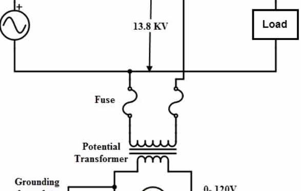
From the image above, the primary side is basically the high voltage side and the secondary side low voltage side. The primary windings of the Potential Transformer are higher than the secondary windings, which can be understood by looking at the image. So this is a step-down transformer. The secondary winding has a voltmeter connected to it to measure the voltage.
The secondary voltage of the PT is normally 110 The volt is designed. Since the voltmeter and other meters of the pit have a high impedance in the potentials coil, a small current will flow in the secondary of the PT. So the PT behaves in a no-load condition Two winding Like a transformer. Because of the low load on the PT VA, The rating is very low. The secondary side is grounded with an edge for safety convenience.
PT’s transformation ratio, like a typical transformer,
V1 / V2 = N1 / N2
If the voltmeter readings and transformation ratios are also known from the above equations, then the high voltage side can be measured.
However, this is the case with the Ideal Voltage Transformer. But that is not entirely true in the case of the actual PT. Because the voltage drops at the primary and secondary windings of the PT. This is usually due to power factor, resistance. Acne has a ratio of phase and phase angle error.
Potential Transformer

Is – Secondary current.
Es – Secondary induced emf.
Vs – Secondary terminal voltage.
Rs – Secondary winding resistance.
Xs – Secondary winding reactance.
Ip – Primary current.
Ep – Primary induced emf.
Vp – Primary terminal voltage.
Rp – Primary winding resistance.
Xp – Primary winding reactance.
KT – Turns ratio = Numbers of primary turns/number of secondary turns.
I0 – Excitation current.
Im – Magnetizing component of I0.
Iw – Core loss component of I0.
Φm – Main flux.
β – Phase angle error.
In the case of current transformers, the primary current Ip Is the vector sum of the excitation current and this current is the opposite of the secondary current which 1/Kt The ratio is qualitative.
So, Ip = ( Io + Is ) / Kt
If in the primacy of PT Vp If the system voltage is supplied then the voltage will drop due to the resistance and reactance at the primary winding where the primary current Ip He will come to This voltage drops Vp After eliminating who Ep Can be found this Ep Equivalent to primary induced E, M, F.
This primary E, M, F will be converted to secondary winding with mutual induction. Here again, Es Voltage will drop due to the resistance and reactance at the secondary windings. As a result, Borden Terminal It will be found in him Vs Is expressed by.
If you don’t know about Burden, note the writing below
Ideally, if the system voltage Vp If there is a secondary voltage of the PT Vp / Kt, But in reality the actual secondary voltage of the PT Vs
So the Ideal Value Vp / Kt And the actual value Vs The difference is the voltage error or the ratio error. This is expressed by the following equation:

Application of Potential Transformer:
- In electric metering systems
- In the Electric Protection System
- In the synchronizing generator with the grid.
- In Impedance Protection of Generators.
Petty Burden: Burden Originally referred to as the parent power that is related to the potentials transformer. Transformer Burden The rating provides the highest value of the apprentice power that the transformer usually performs on certain conditions. Actually, Burden Is the actual apprentice power man with the transformer output load.
Compare Business Electricity Prices | Rates | Supplier Quotes | Saving Tips
INDUCTION MOTOR | WHY DOES THE ROTOR ROTATE | WORKING PRINCIPLE
WORKING PRINCIPLE OF ALTERNATOR
SPEED CONTROL OF DC MOTOR (SHUNT, SERIES, AND COMPOUND)
SPEED TORQUE CHARACTERISTICS OF D.C MOTOR
Wye Delta Transformation | Diagram & Formula | Application


5 comments
[…] Potential Transformer(PT) | Construction | Types | Applications […]
How do I make one of my blog posts appear on another one of my pages?
Contact me at email
Nice article. it’s very helpful for me. I hope you will share more information about potential transformer. Please keep sharing.
Wow, that’s what I was looking for, what a stuff! present here at this website, thanks admin of this web page.|