The current transformer is a device used to measure alternating current. Many people may ask, why to use the current transformer if the current can be measured using a multimeter!
Current transformers are mainly used to measure high current. We know the current is high on the high power line. In this case, the ordinary emitter or multimeter cannot measure this current. Current transformers are used.
Table of Contents
Current Transformer Function:
The basic principle of a current transformer is very much like a normal power transformer. Current transformers like the power transformer also have primary and secondary windings.
When the current is started to flow through the primary winding when the power is transmitted to the transformer, an alternating magnetic flux is generated which causes the alternating current to be induced in the secondary winding.
And let’s explain a little,
When electric supply is provided to the primary coil, a magnetic field is generated around it which collects the secondary coil.
As a result, a mutual induction is created between the primary and secondary coils and the electricity flows to the secondary.

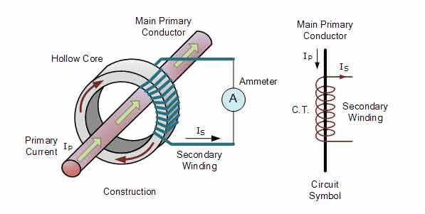
In the case of current transformers, if you look at the image above, you will find that the turnings in the primary windings are very low and the turnings in the secondary windings are high. The secondary winding has an ammeter added to measure current. The question may be, why is the turnover at secondary windings lower than that of primary windings? It has a feature that we will know about in the procedure below.
Procedure
The current transformer is usually step up in case of voltage and step down in case of current. Many people may ask why to step up in case of current transformer voltage and step down in case of current. As I said above there is a specialty that we will now know.
Do you remember Lenz’s formula? If you do not see one more time, the inductive current creates a magnetic field around the conductive wire flowing through the conductive wire, which impedes the origin of the current (ie, the changing flux) by the inductive current.
That is, in the case of current transformers, the number of secondary turns is higher as the current in the secondary will be tied to the current, according to Lenz’s sources.
From the primary and secondary sources, we know,
I1N1 = I2N2
I1 / I1 = N2 / N1
I1/I2 = n
Where
I1 = Primary Current
I2 = Secondary Current
N1 = Number of primary patches
N2 = Secondary punch number
n = The ratio of primary and secondary patch numbers
This is called the transmission ratio of the current transformer.

Normally the current transformer and ammeter are used together which can be understood by looking at the image above. Most current transformer ratios 100/5. That is, the primary current 20 The share is more secondary. So when in the primary conductor 100 Secondary winding will be in the current flow of Empire 5 Empire current will flow.
Again 500/5 In the case of amperes, 500 Secondary to Ampere Primary Conductor 5 Ampere will generate the current which is in the primary 100 The share is high.
Why the current of the current transformer is not kept open or should not be?
We already know from Lenz’s sources that a small amount of current is available in the secondary of the city due to the low turnover. Again, if the primary current of the city is less, the ratio will also be higher in the secondary.
In the normal state of the city, according to Lenz’s formula, primary and secondary windings create magnetic fluxes and bond them to each other. Secondary magnetic flux is lower than the primary magnetic flux and the net magnetic flux is much lower. This net magnetic flux current works on the core of the transformer.
When the secondary winding of the city is kept open, the secondary current will be zero where the primary current of the city remains the same. In this case, there will be no binding magnetic flux in the secondary. Net magnetic flux for primary current only N1I1 Which is too much This higher magnetic flux will create much more flux in the core, which will move the core to saturation level.
Due to too much flux in the core, the secondary winding flux linkage will be too high which will generate a lot of voltage at the secondary terminal of the city. This high volume voltage is very harmful to the secondary terminal and will cause the insulation to fail and accidents can occur.

If excess core flux, hysteresis and AD current loss will be much higher and the temperature of the city will rise. As the oil is being filled in the city, the oil will continue to boil (boil) and evaporate due to the excess temperature. As the steam turns, the housing of the city will wear a lot of pressure and get blasted. This kind of blasting will cause fire and smoke.


4 comments
[…] What Is Current Transformer(CT) | Function | Procedure […]
[…] eyes, ears, and nose, but in the case of electronics, the matter is different. The apparatus can transform any event of the environment into an electrical signal. So it is a device that detects the physical […]
[…] losses are due to energy dissipated in the conductors, equipment used for the transmission line, transformer, sub-transmission line, and distribution line, and magnetic losses in transformers. Technical […]
[…] to the distribution grid located in populated areas. An important part of this process includes transformers which are used to increase voltage levels to make long-distance transmission possible The […]