Basic Electrical Circuit – There are many questions about electrical circuits in various job siblings and written tests. Also, as a student of electrical, it is important to know the electrical circuit well. The topics that will be discussed in this article are:
- What is an electrical circuit?
- The ideal circuit
- Circuit Types
- Open circuit
- Closed-circuit
- Short circuit
- Series circuit
- Parallel Circuits
- Series-Parallel Circuits
Table of Contents
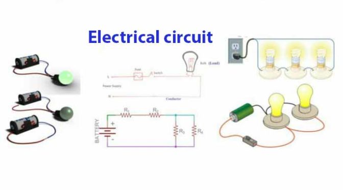
What is an electrical circuit?
An electrical circuit is the means by which electricity can be easily transported through a load and return in another way.
That is, the whole circuit of electricity is called an electrical circuit.
The ideal circuit
An ideal circuit consists of 5 components or components. If a circuit has these 5 components or components then that circuit is called the ideal circuit.
Let’s talk about the 5 components:
An ideal circuit must have an electrical source, either from a generator or from a battery. It will then need a conductor through which the current flows.
Another important component of the circuit is the electric load. A circuit must have a load or resistance such as lamps, fans, peas, etc.
There will be a control device (eg switch) to control or control this load.
There is also a protective device (eg fuse, circuit breaker) to protect the entire circuit.

From the above discussion we learned that in an ideal circuit there are 5 components and they are:
- Power supply
- Conductor cable
- Electric load
- Control devise or switch
- Controlling device / fuse
Circuit Types
There are three types of circuits, namely:
- Open circuit
- Closed-circuit
- Short circuit
Open circuit
Open circuits are those circuits that are not open or disconnected because of which parts of the electrical circuits are not open or disconnected.

In the open circuit, electricity flows from one terminal of the electrical source to the other and cannot return to the other terminal.
Closed-circuit
A closed-circuit is called a closed circuit, where no part of the circuit is open or disconnected and can transmit electricity through the circuit.

Short circuit
The short circuit is when the power is returned from one source terminal to the other in the shortest way due to an error, without power flowing through it.

In the case of a circuit, a short circuit is a fatal error. In such circuits, more current flows than required, which causes much heat and burns if any part of the conductor is lean. And to prevent these burns, we use a fuse or circuit breaker in the circuit. As a result, whenever there is a short circuit, the fuse or circuit breaker opens and opens the entire circuit to the open circuit, thereby avoiding further damage to the circuit.
According to the structure of the circuit, there are three types of circuits
- Series circuit
- Parallel Circuits
- Series-Parallel Circuits
Series circuit
The circuit in which the power flow is connected one by one and the electrical resistances are connected one by one.

Sources of Series Circuits:
Rt = R1+R2+R3+……….. +Rn
Characteristics of Series Circuits
- Electricity flows in all parts of the circuit. That is, I=I1=I2=I3=I4=……..=In
- The total supply voltage of the circuit is equal to the drop or decrease voltage. That is, V=V1+V2+V3+……. +Vn
- The total resistance of the circuit is equal to the mathematical sum of all the resistors connected separately. That is, Rt=R1+R2+R3+……..+Rn
The use of series circuits
- Used in car battery and flashlight.
- Used for various illumination purposes.
- Motor coils are used in series connections and in many cases series circuits are also used.
Advantages and disadvantages of using a series circuit
The disadvantages are more than the advantages of the series circuit-
- There is only one way to power the series circuit.
- Once the load on a series circuit becomes a fuse, the rest stops working.
- The power of the series circuit remains constant.
- Equal power flows to all loads in the series circuit.
Click the link below for details about the series circuit:
Parallel Circuits
A circuit that has multiple paths for the flow of electricity and loads or resistances of the circuit at one fixed point and the other end at another point is called a parallel circuit.

Source of Parallel Circuit-
1/Rt = 1/R1+1/R2+1/R3+ ….. +1/Rn
Properties of Parallel Circuits
The total amount of electricity flowing in the circuit is equal to the sum of the total electricity flowing through different resistances. That is, I = I1+I2+I3+ ……. +In
The voltage available horizontally at each resistance is equal to the supply voltage. That is, V=V1=V2=V3= …….. =Vn But in this case, electricity is divided into each resistance.
Use of Parallel Circuits
- Parallel circuits are used for power supply, distribution system.
- Besides, most of the connected circuits around us are parallel circuits.
- We have parallax connections almost everywhere including our homes, mill factories, office courts, street lights.
Advantages and Disadvantages of Parallel Circuits
- The advantages are more than the disadvantages in the parallel circuit
- In the parallel circuit, there are multiple paths for the transmission of electricity.
- If one load is damaged or damaged, the other load will not be affected.
- Loads of parallel circuits can be controlled separately.
- The power of the parallel circuit is variable.
- The power flows according to the load capacity in the load of the parallel circuit.
Click the link below for details about Parallel Circuits:
Series-Parallel Circuits
The circuit in which the resistances are connected in some series and some parallel is called a series-parallel circuit. This circuit is also called a mixed circuit.

Series- Use of Parallel Circuits
This circuit is used in radio, television circuit, heat controller, compound motor, etc.
Some of the rules required to perform series-parallel calculations
- First, we have to check whether there is a short line or a resistance short in the circuit.
- The internal resistance of the circuit must be calculated in series with the main circuit.
- The voltage source and current source of the circuit must be identified and correctly calculated.
- If the circuit seems complicated then it will need to be simply drawn.
- If there is more than one resistance value in the parallel circuit, then the number of resistances divided by the number of resistances should be taken by the equivalent resistance of the parallel branch.
- When a parallel branch has two resistances, the current value of the current flowing through the resistor must be calculated to determine the current of such branches. For example I1=(It*R2)/(R1+R2) And I1=It-I1 Or I2=(It*R1)/(R1+R2)
Reference by,


1 comment
Whats up this is kinda of off topic but I was wanting to know if blogs use WYSIWYG editors or if you have to manually code with HTML. I’m starting a blog soon but have no coding know-how so I wanted to get guidance from someone with experience. Any help would be greatly appreciated!|