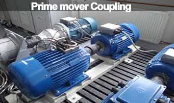
Power Plant Procedures During the discussion, we learned that the shaft of the prime mover is coupling to the shaft of the generator. Today we will discuss the coupling of Prime Mover.
What’s going on in today’s discussion:
- Prime mover Coupling
- Types of Couplings
- Rigid coupling
- Flange coupling
- Hydro or fluid coupling
- Sleeve coupling
- Clamp shaft coupling
- Keyless compression coupling
- Flexible coupling
- Purpose of Coupling.
Table of Contents
PRIME MOVER COUPLING
Prime mover coupling refers to the type of coupling method by which the shafts of two different instruments are fused together. The coupling of a rotating device to another fixed device continues to achieve the rotational speed of the rolling machine.
For example, combining the shaft of a generator with the shaft of a running engine allows it to produce electrical power through the engine. As a result, the mechanical power of the engine is converted to electric power through an electric generator.
Types of Couplings:
Couplings are generally of two types –
Rigid coupling
Flexible coupling
Rigid coupling
This coupling is called rigid coupling, or rigid coupling, because of the rigid connection between the shafts of the two instruments.
The following figure shows some rigid couplings

Rigid couplings are again subdivided into five types-
- Flange coupling
- Hydro or fluid coupling
- Sleeve coupling
- Clamp shaft coupling
- Keyless compression coupling
Flange coupling
This flange coupling is made by combining metal, rubber, fiber, etc., with nut-belts, between the prime mover and the generator shaft at the corners. Usually, flange couplings are used in a unit of power or power generation unit.

The following diagram shows the flange coupling connection method used in a diesel power plant unit:

Hydro or fluid coupling
Hydro or fluid couplings are used in units of medium or high power plants. This type of coupling is driven by hydraulic or fluid pressure.

If the prime mover rotates on the engine or at which angle, the hydraulic coupling fluid rotates with the runner and the driven runner rotates. As a result, the generator connected to the driven runner also rotates at the receiving speed of rotation.
The following figure shows the hydro or fluid coupling connection used between a prime mover and a generator shaft:

Sleeve coupling
Sleeve coupling is basically a basic type of coupling. It is made of a hollow pipe that has the same diameter as the inner diameter and shaft. Depending on the tolerance of the pipe and the shaft size, it has multiple perfect holes. In addition, a key-way is made in the hole to transmit the torque through the key to the coupling, depending on its usage.
Sleeve couplings are also known as box couplings. The following figure shows a sleeve coupling:

Clamp shaft coupling
The clamp shaft coupling is a device used to unite the edges of two shafts.
This is one of the most popular couplings and its design method is also quite simple. For example, the coupling used to connect two pipes or shafts to a water pump is a type of clamp shaft coupling.
The following figure shows a clamp shaft coupling:

Keyless compression coupling
Keyless compression coupling is basically a type of device without a key or knuckles bolt, which is usually screwed into two shaft connections. The following figure shows a keyless compression coupling:

The use of flange couplings and hydro couplings is highest among the above couplings in the power plant.
Flexible coupling
This coupling is called flexible coupling, or flexible coupling, because of the flexible coupling between the shafts of the two instruments.
The following figure shows some flexible couplings:

Universal coupling is usually used to prepare flexible couplings.
The following figure shows a universal combination:

The flexible coupling is divided into four categories based on flexibility, such as:
- Longitudinal Flexible
- Angular Flexible
- Lateral or parallel flexible
- High torsional flexible
Purpose of Coupling:
The following are the objectives of using couplings in a power shaft:
- The coupling provides the mechanical power of the prime mover to another machine by connecting the two shafts.
- Couplings provide two shafts that rotate at an equal speed at angles and lengths.
- The coupling unit connects and submits mechanical power between them.
- Coupling provides the key to the control of slipping by providing a barrier to energy transfer during extra loads.
- When using couplings, it absorbs the heat of friction and ensures a smooth supply.
References:
Power Plant Engineering – Bisbonath Majumdar
Owner Of ICEEET


