Table of Contents
Introduction
In any electrical network, the highest amount of power is used to transmit the power to the load for its operation. A better example of this is an audio amplifier as they transmit the maximum amount of current from the amplifier to the speaker. Similarly, in a radio system, the highest amount of current is supplied from the power amplifier to the antenna. For this, the value of load resistance should be ideal for supply the highest amount of current toward the load. Therefore, the value of load resistance should be the ideal value. If it is either less than or greater than the ideal value the maximum amount of power will not be transmitted. So, to keep up the ideal value of load resistance we developed a theorem I,e maximum power transfer theorem. It assists in detecting the maximum power transmitted to the load.
The amount of power accepted by a load is an important parameter in electrical and electronic applications. In DC circuits, we can represent the load with a resistor having a resistance of RL ohms. Similarly, in AC circuits, we can represent it with a complicated load having an impedance of ZL ohms.
Maximum Power Transfer Theorem
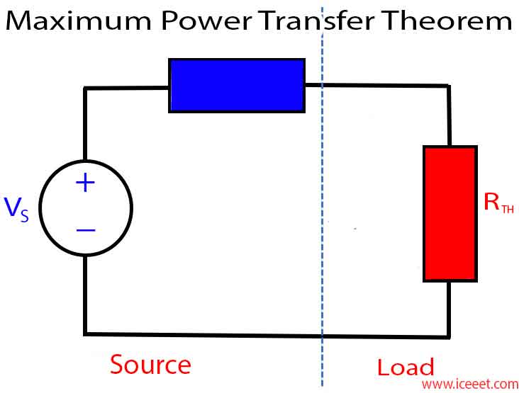
Maximum Power Transfer Theorem can be explained as – A resistive load, being connected to a DC network, receives maximum power when the load resistance is equal to the internal resistance known as (Thevenin’s equivalent resistance) of the source as seen from the load terminals. The Maximum Power Transfer theorem is used to find out the load resistance for which the maximum amount of power would be transferred from the source to the load.
The maximum power transfer theorem is applied to both the DC and AC circuits. The only difference is that in the AC circuit the resistance is substituted by the impedance. The maximum power transfer theorem set their applications in communication systems which receive low strength signal. It is also used in the speaker for transferring the maximum power from an amplifier to the speaker.
Explanation

A variable resistance RL is connected to a DC network as shown in the circuit diagram in figure A below and figure B represents the Thevenin’s voltage VTH and Thevenin’s resistance RTH of the source network. To determine the value of load resistance RL, such that it receives maximum power from the DC source is the aim of the Maximum Power Transfer theorem.
Considering Figure B the value of current will be calculated by the equation shown below

While the power delivered to the resistive load is given by the equation

Putting the value of I from the equation (1) in the equation (2) we will get

PL can be maximized by varying RL and hence, maximum power can be delivered when (dPL/dRL) = 0
However,

But as we know, (dPL/dRL) = 0
Therefore,

Which gives

Hence, it is proved that power transfer from a DC source to a resistive network is maximum when the internal resistance of the DC source network is equal to the load resistance.
Again, with RTH = RL, the system is completely matched to the load and the source, thus, the power transfer becomes maximum, and this amount of power Pmax can be obtained by the equation shown below.

Eqn (3) gives the power which is consumed by the load. The power transfer by the source will also be the same as the power consumed by the load, i.e. equation (3) as the load power and the source power being the same
Thus, the total power supplied is given by the equation

During Maximum Power Transfer the efficiency ƞ becomes

The concept of the Maximum Power Transfer theorem is that by making the source resistance equal to the load resistance, which has wide application in communication circuits where the magnitude of power transfer is sufficiently small. To obtain maximum power transfer, the source and the load resistance are matched and with this, efficiency becomes 50% with the flow of maximum power from the source to the load.
Steps For Solving Network By Maximum Power Transfer Theorem
Step 1 – Remove the load resistance from the circuit.
Step 2 – Find the Thevenin’s resistance (RTH) of the source looking through the open-circuited load terminals.
Step 3 – As per the maximum power transfer theorem, this RTH is the load resistance of the network, that is RL = RTH that allows maximum power transfer
Step 4 – Maximum Power Transfer is calculated by the equation given below.

Practical Application
Consider the practical example of a speaker with an impedance of 8 ohms is driven by an audio amplifier with its internal impedance of 500 ohms. The Thevenin’s equivalent circuit is also shown in the figure.

According to maximum power transfer theorem, the power is maximized at the load if the load impedance is 500 ohms (same as the internal impedance). Or else internal resistance has to be changed to 8 ohms to gain the condition however it is not possible. So this condition is an impedance mismatch condition and it can overcome by using an impedance matching transformer with an impedance transformation ratio of 500:8.
Owner Of ICEEET


8 comments
Touche. Great arguments. Keep up the good spirit.|
Establish new life in a Bali real estate paradise
The Perfect Place to Enjoy and Play
Many thanks, Terrific information!
tripadvisor review writing service do custom essay writing services work how to improve essay writing
Cool, I’ve been looking for this one for a long time
Загрузите Winline и играйте по самым интересным турнирам
Бесплатно скачать Винлайн
Как установить Winline на Ваш ПК